How will liquid cooling support the future state of AI computing? While most now understand that liquid cooling is a prerequisite for the 120 kW NVIDIA racks coming soon, the next step is to consider how to cool even higher power racks. Liquid cooling will remain crucial in managing the escalating chip power and increasing server density as we advance further into the AI computing era.
In this article, we will explore assumptions and calculations for direct liquid cooling a high-power rack, comparing both single-phase and two-phase solutions and leave the reader with specific recommendations. We will outline the temperature and flow rates along with technical specifications needed for designing and cooling high-density racks, aiming for optimal performance and heat management.
Design Requirements for Direct-to-Chip Cooling in 500-kW Racks
We’ll start with an assessment with a set of assumptions as to how this will work in supporting the 500-kW (and greater) racks of the future.
Initial Assumptions and Setup
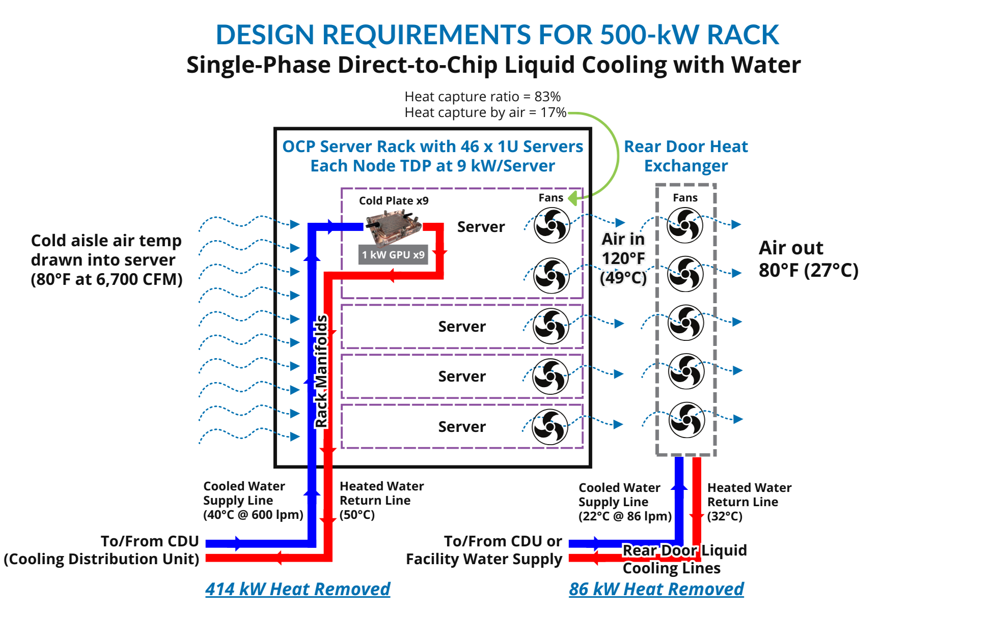
- Total AC power per rack: 500 kW
- Heat capture ratio: 83%
- Rear door heat capture: 86 kW
- Direct-to-chip liquid-cooled heat capture: 414 kW
- Total liquid cooling system pressure drop: 4 psi
Rack Configuration: The design assumes a 48 U OCP rack equipped with 46 1 OU servers, each housing 9 GPUs rated at 1 kW each, resulting in 9 kW per server/node.
Rear Door Cooling Specifications: Air into the rear door at 49°C (120°F), air out at 27°C (80°F), using high-performance active rear door heat exchangers running on water at 22°C (72°F).
Direct-to-Chip Liquid Cooling Specifications (Using Water)
Flow Rate: The 9 kW server requires a coolant flow rate of 13 liters per minute (lpm). The coolant should enter the system at 40°C (104°F) and exit at 50°C (122°F), resulting in a 10°C (18°F) temperature rise. The cold plate ΔP (delta pressure) is 1.8 psi.
Fluid Connectors: The server fluid connectors will use 5/8-inch (16 mm) ID (inner diameter) cooling lines. The connectors can be the LQ8 connectors from CPC that have about 0.25 psi of pressure drop each at the given flow rate, or a generic low-cost liquid cooling connector.
Link: https://www.cpcworldwide.com/Liquid-Cooling/Products/Latched/Everis-LQ8
Manifold Design: The rack manifold, responsible for handling the 600 lpm (158 GPM, or gallons per minute) of flow, consists of a 3-inch (75 mm) square stainless-steel tube with a fluid connector every 48 mm, compatible with the previously mentioned connectors. The manifold’s pressure drop is 0.25 psi, (1.7 kPa) with a velocity of 1.7 m/s (5.6 ft/sec). This manifold is mounted inside the rack, potentially requiring a deep rack for systems with A and B power supply. The power cables will be 1.3 inches (33 mm) in diameter (600A, 480V 3-phase). The coolant lines from the CDU to the rack can be 3-inch wire reinforced flexible plastic tubing for ease of installation. The total pressure drop in the server and manifold is 1.8 + 2 × 0.25 + 2 × 0.25 = 2.8 psi, with an additional 1 psi for pressure drop from the CDU to the rack in a 3-inch flexible tube up to 20 ft long in each direction.
Two-Phase Direct Liquid Cooling Specifications (Using Novec 7000)
An alternative cooling method involves using Novec 7000 for two-phase cooling. In this scenario, the coolant flow rate on the inlet side is significantly reduced to 120 lpm (32 GPM). However, the gas phase coolant flow on the outlet side at 50°C (122°F), is dramatically increased to 24,000 lpm/6,400 GPM/900 CFM (cubic feet per minute).
Direct Comparison
- Inlet Flow: Two-phase cooling uses 5x less flow than water cooling
- Outlet Flow: Two-phase cooling uses 40x more than water cooling (assuming outlet pressure of 1 atm)
Assuming a typical flow velocity of 20 m/s, the inlet line inner diameter should be 0.5 inches (13 mm) and the outlet line inner diameter should be 6 inches (150 mm). These large pipes will be hard to handle in the IT deployment phase. We recommend pipes with an ID of 4 inches (100 mm) or smaller for liquid cooling.
Conclusion
In conclusion, cooling high density racks are limited by more by the power than cooling. If it makes sense to build a MW rack, we can design a water-cooled system for that application.
Additionally, we advocate for water as the best coolant for performance and sustainability. It does not contain any PFAS or “forever chemicals.”
The following figure highlights our recommended approach to support the 500-kW racks of the future:

Figure 1: An OCP server 500-kW rack setup featuring 46 1U servers, each equipped with nine 1 kW GPUs and a rear door heat exchanger.

